Every piece of industrial automation will have schematics (we hope!). These drawings communicate design intent from the engineer to the assembler, troubleshooter, and maintainer. With pages showing power distribution, IO, and safety circuits, a well organized print set can be invaluable for the whole life of the equipment. Knowing how important these are, it surprises me how few resources are available for a person to learn how to create schematics.
In my experience, most of Industry draws schematics with AutoCAD LT, with AutoCAD Electrical and EPlan being dominant in some areas. I learned to use AutoCAD in college by drawing 2D representations of mechanical parts, so naturally, I wasn’t well prepared for electrical schematics in industrial automation when I entered the workforce. Architectural courses abound on the internet, but learning to draw toilets and countertops doesn’t really close the gap either. After years of trial and error, reading and modifying other people’s drawings, and mentorship, I finally had a process and skillset to produce schematics cleanly, efficiently, and with an eye towards the future. In this article, I’m going to share some of my hard won experience to help others learn faster than I did.
If you’re looking to be a pro in record time, check out my full course. There’s a free preview with a few juicy nuggets of pro know how.
Keep It Simple
The first rule is to keep it simple. There are a lot of details that could be included in a schematic – for example: every wire color, gauge, rating – but if the detail isn’t necessary, it’s just visual clutter. It’s important for a technician to be able to quickly understand the machine by paging through these drawings, and more detail makes it harder to understand at a glance. Sometimes a detail like wire color is helpful in the schematics, and gauge is better left for a pull sheet. Sometimes wire color can be safely assumed, as with blue and white/blue for 24VDC and 0VDC respectively.
Leave Space
I often see drawings with every page chock full of devices and wires, and page numbers laid out consecutively. This is harder to read because of the density, and it leaves no room for future changes. Remember that these drawings need to support the machine for its whole life – easily 20-30 years where the control system is concerned, and well beyond that if the control system gets updated. If a page looks like it’s going to get crowded with all the devices you’re putting on it, spread those devices over more pages. And leave unused page numbers for each section of the schematic – power distribution, IO, drives, etc. Someone may need to add IO and a drive in the future.
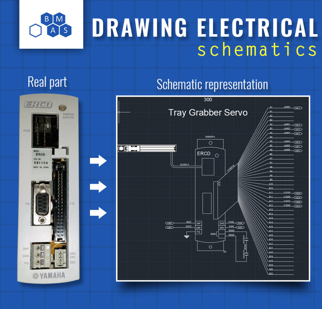
Just Enough Realism
We don’t want our prints to be photo realistic representations of the part we’re drawing, but adding a little detail to components helps them be quickly identified. For example, a schematic representation of a servo drive may start with a rough drawing of how the drive actually looks, then add terminals for the sake of the schematics. Many times, a dwg/dxf file can be downloaded from the manufacturer’s website to provide a good starting point. Don’t forget the first rule when applying this one. Keep it simple!
Reusable Blocks
AutoCAD supports reusing chunks of drawings with what they call “blocks.” The architects use these to add toilets to their drawings without having to draw the toilet every time. We use blocks to add things like prox switches, PLCs, drives, and panel components. Almost every device in my drawings is a block. This saves considerable time and brings a level of uniformity to the drawings.
Blocks can be purchased for this type of drawing, but I’d recommend making your own so they all feel like they belong together.
Templates
It’s hard to start with a blank page. After you’ve gone through the effort of making a drawing set, save it for future use as a template. It doesn’t have to be a special template file. Just keep one of each type of drawing in a folder somewhere and copy that whole folder when you’re starting a new project. You’ll have a title sheet, power distribution, IO, drives, etc already filled in. Now all you need to do is adjust it to the new design.
What’s Next?
Want to learn how? I’ve created a whole video course on this topic, starting from drawing lines and ending with a full schematic complete with block library and templates. This is how I train my employees, quickly getting them up to speed and productive on real projects. You will learn how to efficiently create high quality drawings. This is a highly valuable skill set that’s hard to acquire anywhere else, focused on industry, and lower cost than the archaic courses available in college.

About the Author
Jon is an engineer, entrepreneur, and teacher. His passion is creating and improving the systems that enhance human life, from automating repetitive tasks to empowering people in their careers. In his spare time, Jon enjoys engineering biological systems in his yard (gardening).